Innovtec TruView Live Demo
Try Innovtec TruView Yourself!
TruView technology allows end users to view 3D point cloud data and interact with it while maintaing near-photo quality images of the laser scanned area.
Please follow the brief overview below to get started. For more information and complete details about Innovtec TruView services, please refer to the document below.
Important note: Using a current version of Microsoft Internet Explorer is strongly recommended. We realize it is not the most popular browser choice but works most effectively with the Leica plug-in that allows TruViews to be seen in a browser. The TruViews plugin is Windows only at this point in time.
- Open Microsoft Internet Explorer
- Download the TruView plugin
Go to https://innovtecftp.sharefile.com/d/s3c43aec33f244989 and fill the requested information (email, name and company) then press the “Continue to download page” box. On the next screen press the Download box to download the TruView Setup and follow simple instructions to complete the free viewer download. - Click the link for a live demo of TruView.
Go to https://www.innovtec.com/TruViews/TruView_Demo/SiteMap.htm
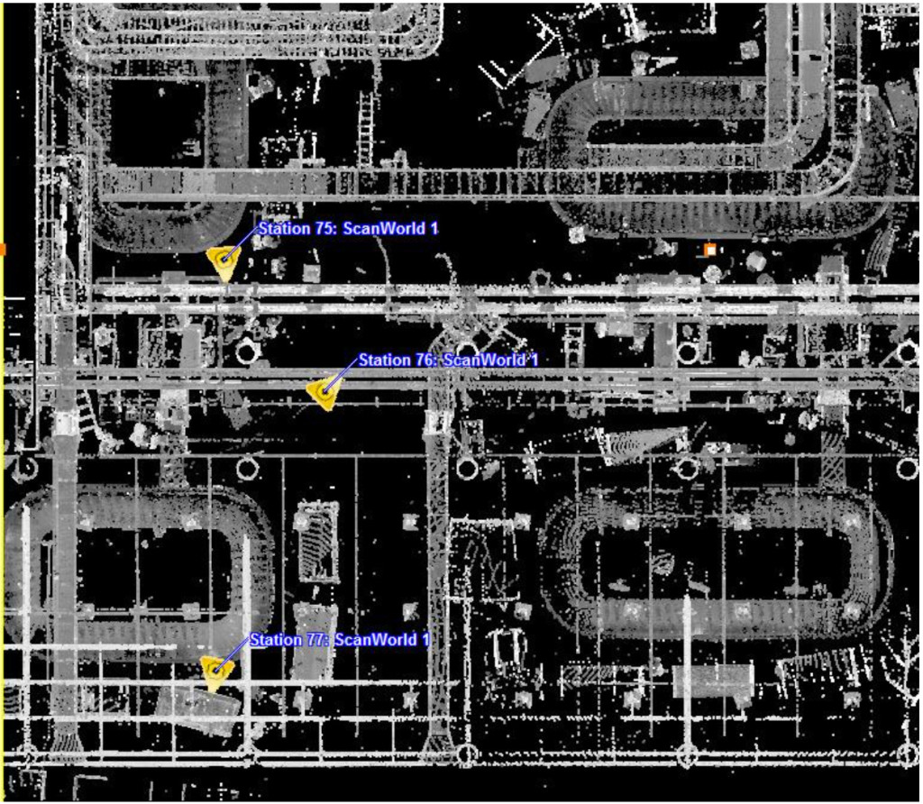
Clicking this link brings up a plan (overhead) view. Next, click on any one of the yellow triangles labeled “Station 75: ScanWorld 1, Station 76: ScanWorld 1 or Station 77: ScanWorld 1”. You should now be able to view, measure, and label elements inside an active TruView showing a mechanical room environment. If you have any questions, please contact us.
ABOUT INNOVTEC TRUVIEW
1. Scanning and TruViews – Innovtec will scan the areas of interest and provide TruView images of each of the scan positions – from floor to upper ceiling of interstitial areas.
1.1 Panoramic TruViews – “TruViews” consist of fully interactive 360° panoramic views of all objects scanned from the vantage point of the scanner. These views are visible on a standard PC with an easy-to-use no-cost downloadable plug-in software application. Each TruView contains actual visual representations of all areas scanned. This includes all architectural, MEP, structural, and electrical components visible to the human eye. Each object will be recorded in their true 3D position in space, as well as their position relative to adjacent objects.
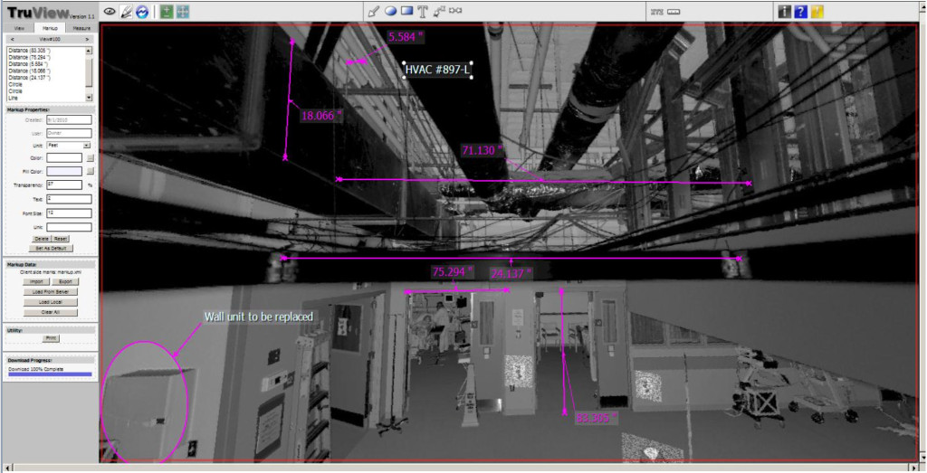
1.2 Example TruView Image – The following is an illustration of a segment of a 360° window of a scan in a hospital. It shows the point cloud from the laser scanner represented on a computer monitor. Each pixel on the screen is mapped to a 3D point in the point cloud which is associated with a unique 3D coordinate in space. Each view is capable of being viewed 360°horizontally and 270° vertically. You can pan in any direction and zoom in and out in any view. True 3D measurements and annotations can be appended to each view. The upper portion of the illustration shows the “interstitial area” between the hanging ceiling (“T” Bar with acoustic ceiling tile) and the upper overall ceiling of the area of interest.

Figure1.2 Example of TruView showing interstitial area (at top) and room features with measurements and annotations.

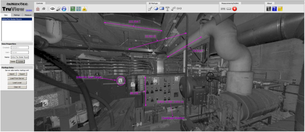
Figure 1.2 Example of TruView showing a 3D laser scan in a boiler room – with measurements and annotations.

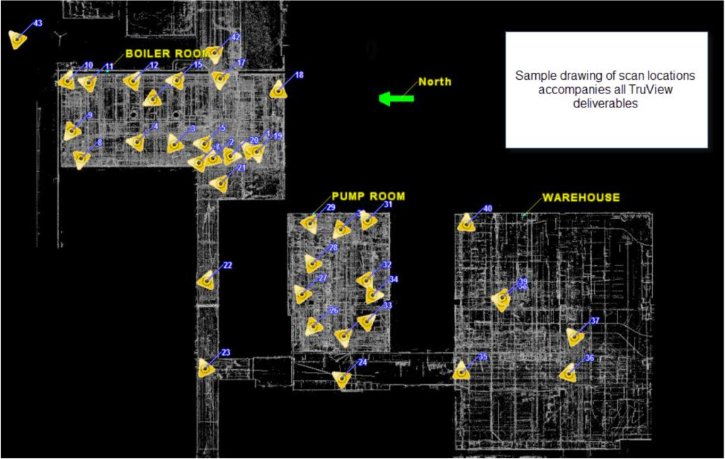
A “key map” allows the user to click and choose viewpoints from any scan position easily.
1.3 Full panoramic views of all scanned scenes from each position of the laser scanner may be seen on your computer screen. You can add annotations, arrows, take measurements and 3D coordinate values from any object or point on your screen. By using this information, all project participants can easily and quickly share project information with each other; and make design decisions without having to go to the job site or to take hand measurements.
1.4 TruViews have been proven to be a tremendous time saver for all project team members and have shown to be an invaluable tool to eliminate design errors and virtually eliminate subsequent change orders due to interferences or “clashes” between design and actual field conditions.

